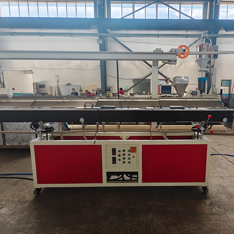
Filament diameter inconsistency remains the leading cause of extruder jams and failed print jobs. When your material exceeds standard ±0.03mm tolerances, you face inconsistent print layers. Rejected material batches quickly destroy your profit margins. Transitioning from basic DIY setups to commercial production demands a major operational shift. Manufacturers must move away from manual observation and guesswork. Instead, they require automated, closed-loop diameter control to guarantee perfect dimensional accuracy. We wrote this guide to provide an evidence-based framework for solving these manufacturing challenges. You will learn how to evaluate extrusion equipment properly. We will explain how to manage vital thermal and mechanical variables during production. Ultimately, this article helps you select a reliable extrusion setup for scaling your output confidently.
Key Takeaways
**Tolerance Standards:** Commercial viability demands a consistent diameter tolerance of ±0.03mm or better; anything worse impacts final print quality and brand reputation.
**The Control Triad:** Precise diameter relies on balancing three core metrics: consistent melt pressure, managed cooling gradients, and synchronized haul-off (puller) speeds.
**Automation is Mandatory:** True production-grade consistency requires dual-axis laser micrometers integrated into a closed-loop PLC system.
**Equipment Selection:** Upgrading a plastic filament production line requires evaluating screw design (L/D ratio), melt pump integration, and multi-stage cooling zones over baseline extrusion speed.
The Business Cost of Poor Filament Diameter Control
You lose money rapidly when material dimensions fluctuate. Minor variations cause major disruptions during quality assurance protocols. Ovality prevents filament from feeding through printer gears correctly. Melt surging creates uneven spool weights. These defects lead to entire material spools failing QA checks. You then face increased raw material waste and skyrocketing energy costs. Scrap material continuously eats into your daily profit margins.
Standard FDM/FFF printers demand highly precise inputs. The mechanical reality punishes poor dimensional accuracy ruthlessly. Under-extrusion creates weak, brittle parts. Over-extrusion leaves ugly blobs on outer surface walls. Printers expect exactly 1.75mm or 2.85mm targets constantly. Any deviation ruins the final print geometry completely.
Customers notice these extrusion defects immediately. End-users actively share their bad experiences online. Prosumers run expensive machines. Industrial print farms operate continuously across multiple shifts. They will blacklist your brand quickly if quality drops. Hotend clogs destroy hours of valuable print time. Inconsistent layer adhesion ruins structural parts. Rebuilding brand trust takes years in this competitive industry.
Furthermore, you must evaluate vendor marketing claims carefully. Many equipment manufacturers advertise ±0.01mm tolerances blindly. You should remain highly skeptical of these numbers. Proper filament diameter control requires sophisticated inline feedback mechanisms. Vendors must explain their internal measurement loops clearly. They often cite theoretical limits rather than continuous production data. Always demand hard proof.
Achieving perfect dimensions involves balancing multiple mechanical forces simultaneously. We classify these into three core metric areas. You must master the extruder side, the cooling side, and the puller side.
Polymer Melt Flow and Pressure (Extruder Side)
Consistent raw material preparation matters immensely. You must dry your pellets thoroughly before processing. Proper mixing ensures uniform material density. Screw RPM fluctuations cause immediate downstream problems. Inconsistent heater band temperatures create uneven melting profiles. Lacking PID control leads to wild thermal swings. These factors combine to cause melt surging. Surging ruins diameter consistency instantly. A modern 3D filament extrusion machine utilizes precise thermal management to prevent this.
Thermal Gradients (Cooling Side)
Cooling molten plastics too quickly creates severe physical defects. We call this phenomenon "shock cooling." It causes internal voids. It creates severe ovality issues. Internal stress builds up rapidly inside the strand. You must employ multi-stage water baths. The process starts warm and finishes cold. Gradual cooling stabilizes the polymer state safely. Your filament retains a perfectly round shape.
Tension and Haul-off Dynamics (Puller Side)
The haul-off tractor pulls the molten plastic forward. The speed ratio matters deeply here. This ratio between the extruder screw and the tractor dictates the final drawn diameter. High tension stretches the filament thinner. Low tension allows it to swell uncontrollably. You face mechanical risks continuously. Slippage in the puller belts causes sudden thickness spikes. Uneven belt pressure distorts the roundness. You must maintain perfectly synchronized speeds.
Evaluating a 3D Printer Filament Extrusion Line for Precision
Standard plastics equipment often fails for 3D filament. You need specialized engineering. Upgrading requires evaluating several crucial components carefully.
Screw Design and L/D Ratio
Standard injection molding screws do not work well. They provide inadequate mixing for continuous extrusion. You must look for specific L/D ratios. Industry standards recommend 28:1 to 32:1 ratios. These longer screws optimize continuous melt flow. They protect shear-sensitive polymers from thermal degradation.
Integration of Melt and Gear Pumps
Pressure fluctuations happen naturally inside an extruder barrel. Melt pumps solve this problem efficiently. They sit between the screw and the die. They isolate the die from screw pressure changes. This isolation provides a volumetric, pulse-free flow. Pulse-free flow is absolutely critical for diameter stability.
Closed-Loop Laser Measurement Systems
Manual micrometers belong in the past. You absolutely need inline laser measurement. Systems must use dual-axis or tri-axis laser micrometers. They scan the filament thousands of times per second. The PLC interprets this real-time laser data instantly. It then micro-adjusts haul-off speeds dynamically. This continuous feedback loop ensures tight tolerances. A proper 3D printer filament extrusion line relies heavily on this feedback loop.
Die Head Engineering
Die design requires extensive polymer knowledge. The die head must match the specific rheology of your target material. PLA flows differently than high-temp PEEK. Proper internal geometries minimize die swell. Smooth flow channels prevent material stagnation. This engineering keeps the melt stream stable upon exiting the nozzle.
Equipment Feature Comparison
Feature Category
Standard Extruder Systems
Precision Filament Lines
Measurement
Manual calipers or single-axis laser
Dual/Tri-axis inline laser micrometers
Pressure Control
Relies solely on screw RPM
Integrated melt gear pump
Cooling System
Single cold water trough
Multi-stage graduated thermal baths
Automation
Open-loop manual adjustments
Closed-loop PLC dynamic feedback
Special Considerations for Advanced and Multi-Material Extrusion
The market increasingly demands specialized materials. Standard PLA production is relatively simple. Advanced materials require complex mechanical adaptations.
Managing Multi-Color Extrusion
Aesthetic materials dominate consumer markets today. Achieving perfect three-color filament extrusion involves significant co-extrusion complexity. You must balance three separate melt streams perfectly. They merge into a single 1.75mm profile. Doing this without distorting the roundness proves difficult. You need specialized co-extrusion die heads. You also require highly synchronized satellite extruders. Pressure matching prevents one color from overpowering the others.
Filled and Composite Materials
Engineering applications demand composite materials. Carbon fiber additives increase strength. Glass fiber improves rigidity. Wood-filled polymers offer unique visual aesthetics. These fillers alter the die swell significantly. They require adjusted cooling distances. Abrasive fillers wear down standard metals quickly. You must use hardened steel components. Hardened screws and dies maintain diameter over time.
System Scalability
Commercial producers need flexible equipment. You should assess machine scalability carefully. Consider whether the system can seamlessly switch between standard polymers and advanced composites. Simple die and screw swaps save hours of downtime. Modular designs allow rapid changeovers. This flexibility maximizes your overall production uptime.
Chart: Material Cooling and Processing Requirements
Material Type
Die Swell Risk
Cooling Requirement
Hardware Needs
Standard PLA
Low
Gradual warm-to-cold bath
Standard nitrided screw
Carbon Fiber Nylon
High
Extended warm stabilization
Hardened steel die/screw
Co-extruded Silk
Medium
Precise multi-stage zones
Specialized co-extrusion die
Shortlisting Logic & Implementation Risks
Buying industrial equipment requires diligent vetting. Do not rely solely on marketing brochures. You must prove the capability before signing any purchasing agreements.
Proof of Concept
Demand hard evidence from potential vendors. Require them to run a continuous 8-hour test. They must use your specific resin formulation. Ask for the complete data log afterward. Analyze the diameter deviations yourself. This data reveals true system stability under actual operational stress.
Integration Realities
Fragmented systems cause massive headaches. Sometimes the laser micrometer cannot natively communicate. The tractor puller PLC must understand the laser signals instantly. If they use different protocols, the feedback loop fails completely. Ensure seamless native integration across all sensors. A modern plastic filament production line demands unified control architectures.
Operator Training
Automation does not replace skilled operators. Automated systems still require human oversight. Operators must understand PID tuning thoroughly. They must perform accurate die centering manually. They need to manage water bath temperature profiling actively. Proper training prevents expensive scrap generation.
Sensor Latency: Slow communication delays speed adjustments, causing wavy filament.
Mismatched Geometries: Incorrect extruder screw designs cause severe material degradation.
Inadequate Cooling: Short water bath lengths fail to cool high-speed production safely.
Thermal Hunting: Poorly calibrated PID controllers cause continuous temperature fluctuations.
Next Steps
You must define your material portfolio clearly. Calculate your required kg/hr output accurately. Draft a detailed RFP focusing heavily on closed-loop feedback capabilities. Prioritize data logging and sensor integration above raw machine speed.
Conclusion
Controlling filament diameter requires profound attention to detail. It is never a matter of flipping a single switch. It represents a holistic orchestration of heat, pressure, and automated tension. You must align these forces perfectly. We recommend prioritizing your investments wisely. Sensor quality matters more than raw output. PLC integration dictates your final material quality directly. Raw extrusion speed means nothing without tight tolerance control. High speeds simply produce unsellable scrap faster if left unmanaged.
Actionable Steps for Production Upgrades:
Audit your current dimensional failure rates and identify peak defect times.
Determine acceptable maximum output speeds for your specific heat-sensitive polymers.
Evaluate vendors based on continuous data logs, avoiding theoretical brochures.
Invest heavily in operator training programs focusing on PID and die management.
FAQ
Q: What causes 3D printer filament to become oval instead of round?
A: Ovality usually stems from improper die design or mechanical stress. Excessive puller tension before the plastic core solidifies stretches the material unevenly. Directional cooling also causes severe issues. If water jets hit one side harder than the other, the plastic warps. Multi-stage, uniform water baths solve this defect.
Q: Can a single-screw 3D filament extrusion machine achieve ±0.02mm tolerance?
A: Yes, it is entirely possible. However, the machine requires specific high-end upgrades. You must equip it with a precise melt pump. Consistent raw material feeding is non-negotiable. Furthermore, it demands an active closed-loop laser feedback system to adjust puller speeds continuously in real-time.
Q: Why is my filament diameter fluctuating in a sine wave pattern?
A: This sine wave pattern indicates "surging." Surging has several root causes. Uncalibrated PID temperature controllers cause melt viscosity to fluctuate constantly. Irregular pellet feeding also creates uneven barrel pressure. Finally, a lack of a gear pump fails to stabilize the die pressure, passing variations directly to the filament.
We are a professional manufacturer of plastic machines and we have devoted ourselves to the development, research, and production of plastic machinery for more than 20 years.